|
The principle of electromagnetic induction was discovered by Michael Faraday (1791-1867) in 1831. Induction coils were used widely in electrical
experiments and for medical therapy during the last half of the 19th century,
eventually leading to the development of radio in the 1890's. For more
information on the application of induction coils in radio, see my
chapter on spark coils
in the "The Wireless Age" section of this web site.
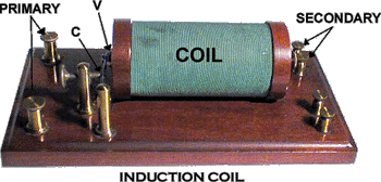
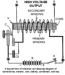
An induction coil essentially operates like a big
buzzer: The interrupter's contacts (C), are wired in
series between the battery (B), and the coil. The contacts are
closed in their resting state. When power (B) is applied, the
coil is activated which produces a magnetic field at the metal core of
the coil. The magnetic contact arm (V) is pulled toward the core,
opening the interrupter contacts and breaking the circuit. The falling
magnetic field relaxes its hold, the contacts close, and the entire
cycle repeats.
The rising and falling magnetic field of the primary
coil induces a high voltage across the secondary.
|
 |
 |
|
How They Were Used
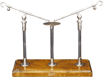
Induction coils were used in many different kinds of experiments. In
order to facilitate easy access to a variety of devices, an
experiment table was commonly used. A typical table is shown at
the right. The output of the coil was connected to the vertical
brass uprights and the connections could be adjusted safely using
the insulated handles.
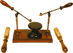
The "hand electrodes" shown in the photo were
used in experiments where the output of the coil was connected to a
person (not directly - through a rheostat!) Many people of the time
believed the mild electrical shock to be therapeutic. An entire
industry of "quack" medical devices was born from the invention of
the induction coil.
|
8" Experiment Table |
A specialized type of induction coil called a
Rhumkorff coil was used in early radio transmitters - so
called "Spark" transmitters in the "teens". You can see some
examples of these spark coils by clicking
here. |
High Voltage Experiment Table
and Hand Electrodes
1868
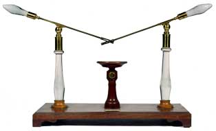
Henly's Universal
Discharger
J. Newman, Lisle Street, London
1st Qtr, 19th Century
Mahogany base
measures 15" x 6"; the glass pillars are 8-3/4" in height. See
Public and Private Science: The King George III Collection pg 520,
fig. E213. |
|

Grenet Cell
1885 |
Powering an Induction Coil
The photo at left is of a Grenet
cell. These early acid jar batteries was used widely in electrical
experiments during the last quarter of the 19th century and
were commonly used as the primary power source for induction coils.
For more information and a photo of Thomas Edison using the cell,
click
here.
Some other examples of induction coils in my collection are shown
below.
|
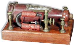
Griggs Conical
Electromagnetic Machine
1873 |
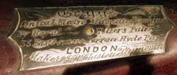
Griggs Machine
Label |
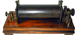
Rhumkorff coil (signed)
1850 |
|

William Sturgeon Mercury Interrupter
English
1838
Described in "Annals of Electricity, Magnetism and
Chemistry" Vol. III, London 1838 pgs 331-334, Plate Il figs. 15 and 16.
|

William Sturgeon Mercury Interrupter
English
1830 |

Primitive Hand-wound Interrupter
English
1840
The brass and ivory
handle turns a cogged wheel and the axle of a double ratchet,
which engages the cogs is connected to a horizontal copper bar.
The axle and the ends of the horizontal bar are bent to dip in
mercury cups. On rotating the crank handle, the pinion wheel
causes the bar to execute a rapid see-saw movement which then
causes the end pieces to make and break contact rapidly with the
measuring in the two side cups. Described in The Scientific
Apparatus of Nicholas Callan , Mollan and Upton, 1994 pg. 84-85,
fig. 102. . |
|
|
|
|

Compound Magnet and Electrotome
Daniel Davis
1840
Invented
by Charles Page in 1838 (see Page's biography: Physics, Patents
and Politics by R.C. Post pg. 24) but patented in 1868. First
described by Page in "Magneto-Electric and ElectroMagnetic
Apparatus and Experiments, " American Journal of Science,
(1839), pgs 252-68, figs. 1-7.
|
|

Double Helix and Vibrating Electrotome
Daniel Davis
1848
Described in slightly different form in Manual of Magnetism pg
301 fig. 182. (2nd Ed). Invented by Charles Page and patented in
1868 but developed in 1838.
|

"Dr. C.B. Barrett
Medico Electro-Medical Machine"
Likely Daniel Davis
1848
Pictured and
described in Manual of Magnetism (pg. 301 fig. 182)
|
|

Double Helix and Vibrating Electrotome
Daniel Davis
1842
This is a larger
version described in Davis's Manual of Magnetism pg. 301 fig.
182 (2nd Edition). Included are two rosewood and brass medical
shock handles and battery (some paint worn off) as shown in
Davis's Catalog pg. 38, fig 182.
|

Hinds and Williams
Double Helix and Vibrating Electrotome
Likely Daniel Davis
1848
(See
pg. 301, fig. 182 of Davis' Manual of Magnetism 2nd Edition. )
|
|

Pike's Vibrating Magnetic Instrument for
Medical Use
Benjamin Pike, Jr.
1848
Signed
by Benjamin Pike, Jr., on bottom of mahogany base with trade
card reading "Benjamin Pike, Jr., Optician, Importer and
Manufacturer of Mathematical and Philosophical Instruments, No.
294 Broadway, New York". This machine is described in
Pike's Catalog, on pg. 47 of Volume II, fig. 469. |

PIKE'S ROTARY MAGNETIC MACHINE
Benjamin Pike, Jr.
1848
An electromagnetic
machine and battery and with trade card attached to inside cover
of walnut box measuring 16" x 6" x 7". Trade card reads
"Benjamin Pike, Jr. Optician, Importer and Manufacturer of
Mathematic and Philosophical Instruments, No. 294 Broadway, New
York". Elaborate label also an inside top lid of box reads
"Pike's Rotary Magnetic Machine introduced Nov. 1843 " with
extensive instruction on use.
This machine is
described in Pike's Catalog Vol. II on pages 44- 47 and pictured
in fig. 468. The device is featured on the front wall (in a
large advertisement) of Pike's first shop in 1848 as seen in the
woodcut frontispiece in his catalogs of 1848 and 1856.
|
|

"DR. S.B. SMITH'S 18 POUND MAGNETIC CURRENT
AND 6 POUND DIRECT CURRENT MACHINE"
1845
Box made of walnut
measuring 6" x 3-1/2 " with electromagnetic machine and
accessories. Label of inside cover reads "Dr. S.B. Smith's
Pocket Magnetic machine of very strong Intensity" with
instructions. |

NEW PORTABLE MAGNETO-ELECTRICAL MACHINE FOR
MEDICAL PURPOSES
Benjamin Pike, Jr.
1848
Described
in Pike's Catalog Vol. II pg. 49 fig. 471. |
|

NEW PORTABLE MAGNETO-ELECTRICAL MACHINE FOR
MEDICAL PURPOSES
Benjamin Pike, Jr.
1848
Described in Pike's Catalog Vol. II pg. 49 fig. 471 |

"DR. S.B. SMITH'S DIRECT AND TO-AND-FRO
CURRENT ELECTRIC MACHINE"
1850. |
|

FOSTER'S IMPROVED ELECTROTOME,
"James Foster, Makers, Cincinnati, O"
1850
Has green label
with instructions on inside lid of mahogany box measuring 7-1/4"
x 7". Electromagnetic medical device with separate glass and
wood battery also signed. Fine condition; box has been restored.
|

ELECTROMAGENTIC MEDICAL MACHINE
"Manufactured for G.M. Boardman by William Mead 409 Broad Street, Newark,
N.J."
1840's
Contained in_ wooden box measures 6-1/2" x 6" x 3-1/2" with
primitive copper-zinc battery. |
|
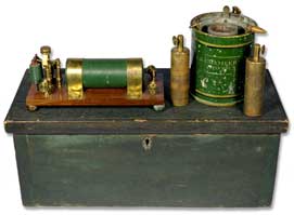
Double Helix and Vibrating Electrotome Complete with Battery and
Handles in Wooden Box
N.B. Chamberlain
1840's
Identical to
Davis set on pg. 301, fig. 182 in the Manual of Magnetism.
Extremely rare in it's completeness.. |
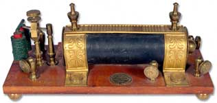 "DR. C.B. BARRETT MEDICO ELECTRO-MEDICAL
MACHINE"
New York, 1848
Pictured and
described in the Manual of Magnetism pg. 301, fig. 182 and
likely made by Davis but signed by "Barrett". |
|
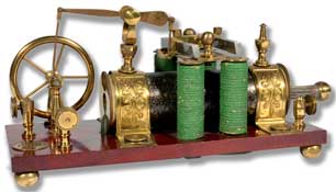 JEROME JEWELL: ELECTRO-MEDICAL DOUBLE HELIX
AND RECIPROCATING ARMATURE ENGINE
1848
A fine and early
reciprocating engine with four poles mounted atop the helix
instead of a vibrating electrotome. Clearly in the style of
Daniel Davis with typical components, including four brass ball
feet supporting the base. Signed. "Jerome Jewell, Manufacturer
of Galvanic Instruments, Bristol, Conn. |
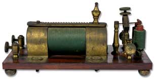
Double Helix and Vibrating Electrotome
Daniel Davis, Jr.
1840's
Missing a finial.
Illustrated in the Manual of Magnetism on pg. 301, fig. 182.
|
|
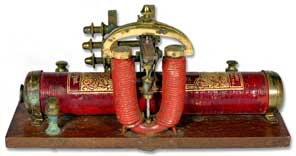 "DR. S.B. SMITH'S DIRECT AND TO-AND-FRO
CURRENT AUTOMATON ELECTROMAGNETIC MACHINE"
New York, Patented June 4, 1850
The electromagnetic device measures 7-3/4" x 3" and instead of
an electrotome as the interrupter, this device has a rotating
engine similar to "Pike's Rotary Magnetic Machine"
|
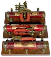
A36
|
|
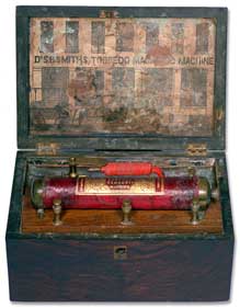 "DR. S.B. SMITH'S TORPEDO MAGNETIC
MACHINE"
1840's
Label on inside cover reads "Dr. S.B.
Smith's Torpedo Magnetic Machine" and shows a horse and buggy in
front of Dr. Smith's establishment. . A primitive battery is
included in the box as well. |
 "HINDS AND WILLIAMS, MANUFACTURER'S OF
APPARATUS TO ILLUSTRATE MAGNETISM, GALVANISM, ELECTRODYNAMICS,
ELECTROMAGNETISM, MAGNETO ELECTRICITY, THERMOELECTRICITY, NO.
313 WASHINGTON STREETS, BOSTON, MASS"
1850
A vibrating electrotome
and double helix complete in walnut box measuring 10" x 7"x 7"
with purple backed label with gold lettering as above on inner
lid. The electromagnetic instrument measures 4-1/2" x 6-1/2"
rosewood base, the green painted circular battery is 4-1/4" (d)
and 6" (h). Accessories include: electro-shock handle; an
electromagnetic glass eye-cup and a natural sponge.
|
|
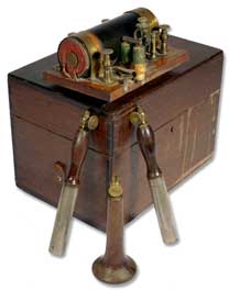
Double Helix and Vibrating Electrotome
C. Williams, Boston
1860
Very similar to
above "Hinds and Williams" except missing inner label to box.
Battery is missing, accessories include rosewood electromagnetic
eye-cup and two rosewood electro-shock handles. The
electromagnetic device is on a walnut base and measures 6-5/8" x
4-1/2" and is stamped "C. Williams, Boston" on brass support
straps holding coil which is painted red. |
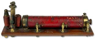
VIBRATING MAGNETIC MACHINE
signed "H.H.
Sherwood, M.D."
1840's
Pictured and described in
the Manual for Magnetizing with the Rotary and Vibrating
Magnetic Machine in the Duodynamic Treatment of Diseases, by H.H.
Sherwood, M.D. (9th Ed), New York, 1847 on page 31.
|
| |


