| Contact |
| Back | Next | Home |
Galvanometers & Meters
Galvanometers were the first instruments used to determine the presence, direction, and strength of an electric current in a conductor. All galvanometers are based upon the discovery by Hans C. Oersted that a magnetic needle is deflected by the presence of an electric current in a nearby conductor. When an electric current is passing through the conductor, the magnetic needle tends to turn at right angles to the conductor so that its direction is parallel to the lines of induction around the conductor and its north pole points to the direction in which these lines of induction flow. In general, the extent to which the needle turns is dependent upon the strength of the current.
|
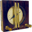
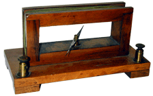
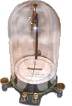
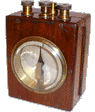
André-Marie Ampère, (1775-1836), is credited with the invention of the galvanometer in 1824. The earliest galvanometers were literally constructed of a compass surrounded by a coil of wire (see example at right). These meters were called tangent galvanometers because the tangent of the angle of deflection of the needle is proportional to the strength of the current in the coil (at this point in time it was impossible to construct a meter whose needle deflection was directly proportional to the current under measurement). |
|
|
|
|
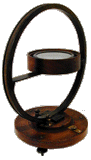
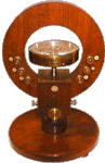
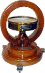
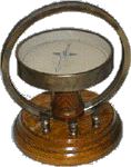
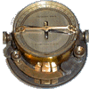
Unfortunately, simple galvanometers such as the Struers model shown above were inaccurate and inconsistent in their readings. By placing the compass at the center of a precisely calculated circle, accuracy could be improved substantially (see left). Other improvements were added later including replacing the compass with a specially designed meter movement, adding leveling screws, etc. These large stationary-coil type galvanometers were used as the standard current measuring instrument into the last quarter of the 19th century. Additional examples of tangent galvanometers are shown below: |
|
|
|
|
|
|
 Knott Tangent Galvanometer |
 Early Tangent Galvanometer |
 Early Rectangular Tangent Galvanometer |
 University Supply Tangent Galvanometer |

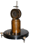
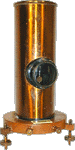
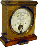
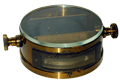
Reflecting Galvanometers
|
|
|
|
|
|||||
|
|
|
|
||||||
|
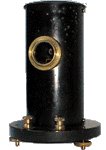
String Galvanometers |
|
|
||||||
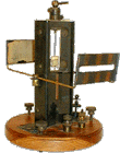

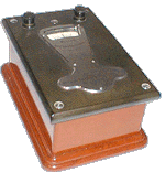
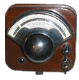
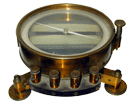
d'Arsonval Galvanometers
Early d'Arsonval Meters:
|
|
|
|
|
|
|
|
|
|
|
|
|
||
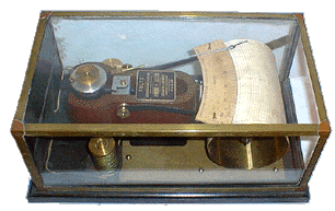
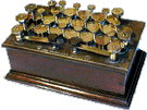
Resistance Coils
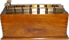
A Resistance box contains an assortment of coils of known resistance, with the ends of the coils connected together and brought out to brass plates mounted on the top of the box. To configure the box for a specific resistance, brass plugs are inserted into the plates at the appropriate locations. The plugs "short out" one or more of the coils, resulting in the desired resistance at the terminal of the resistance box.
Some boxes, such as the King Mendham bridge below, contain coils wired into a special circuit known as a "bridge". The bridge makes very accurate resistance measurements possible by balancing an unknown resistance against three other known values.
|
|
|
|
||||
|
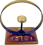
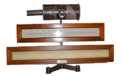
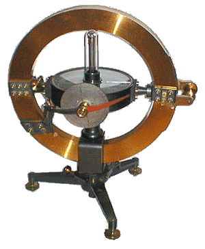
This incredible piece is over 21" tall. The coil is 16" in diameter and can be rotated on two axes around the needle assembly. The force on the compass needle decreases as the coil is tilted since that decreases the component of the field in the plane of the needle. These instruments were used in the 1870's to measure the large currents produced by power station dynamos.
|
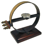
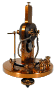
Beautiful Precision Sine Galvanometer
|
|
||||

Bibliography:
The Hutchinson Dictionary of Scientific Biography
Hawkins Electrical Guide, Vol 2 pp 431 - 464
| Contact |
| Back | Next | Home |